Background Information
Engineers Week
Every year, there is a week called Engineers Week. The idea is to get K-12 students interested in engineering ideas, classes, majors, and careers. Some companies get involved - hosting tours, giving presentations, or otherwise exposing students to STEM.
This week comes from the idea that the earlier children are introduced to engineering, the more excited they'll be to learn about it. To learn more, see the DiscoverE Website.
Girls’ Day
One day within Engineers Week is called Girl Day. The purpose of this day is to introduce a young girl to engineering. The perception that STEM, and specifically engineering, is only for boys is challenged for the girls that participate.
MESA Program
On SDSU's campus, there is a program called the Mathematics, Engineering, Science Achievement (MESA) Program. This program works to help students learn and achieve by providing on-campus resources and events. The MESA Program also engages in outreach events to help younger students become interested in STEM. To learn more about the MESA Program, visit their website here.
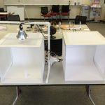
On Girls Day 2016, the MESA Program brought 30 middle school girls to SDSU's campus for a variety of STEM workshops and discussions. build IT was one of the locations the girls visited. We hosted the girls for roughly an hour, during which they listened to a presentation on 3D printing, watched some 3D printers print, scanned their friends with our handheld 3D scanner, and painted some 3D printed bracelets. This post is about the design and creation process of the bracelets.
There was a news article about the MESA program and Girls Day! You can read it here!
The Design
Design Requirements
We spent a long time trying to decide what object to print for the girls. We wanted everyone to take something home, and for them to be able to decorate them while they were here. We also wanted the object to be STEM related. Whatever it was, we were going to work in a brief talk on it during our presentation. After discussing various different objects (keychains, planters, and model planes were all considered!), we finally settled on using a flexible filament to create bracelets.
We knew that there were going to be about 30 girls, plus chaperones. We wanted to have enough bracelets so that there was one for each girl, plus their chaperones, plus some extras. We ended up deciding on 45 bracelets.
Next, we knew that we needed to be able to 3D print everything within the three weeks that we had before the event, so the bracelets had to be physically small enough to allow us to print 45 during the hours we were open. In addition to that, we wanted them to use a small enough amount of plastic such that we could get all 45 made from a 1kg spool. (Filament usually comes in spools of 1kg, so the purpose of this was to spend the least amount of money.)
To summarize, our requirements were:
• A bracelet that was entirely 3D printed
• 45 bracelets were needed
• Printable within 3 weeks only during open hours
• Use only 1kg of plastic for all bracelets
• STEM-related in some way
How big is your wrist?
Since we were set on bracelets, the next question was how big do they need to be? We didn't know which grade the girls would primarily be from, just that they were middle schoolers. Middle school in San Diego is grades 6-8, or approximately ages 10-14.
So just how big is a 10-14 year old girl's wrist? There were some websites that had sizing charts for jewelry, like this one, but we weren't sure how accurate they were.
We decided to start polling people who came in to build IT about their wrist sizes. We used string and a ruler and recorded wrist sizes. We decided that the average wrist size was probably close enough for the middle schoolers. It ended up being right around 7 inches, or about 178 mm.
What will go on the bracelet?
One of our design requirements was that the bracelets be STEM-related in some way. We talked about getting rid of that requirement and writing "buildIT" on them, but that seemed too much like self-promotion and not enough like education. We found a very cool bracelet design on Thingiverse, but we wanted the bracelets to be designed by us.
We eventually settled on a solar system. We decided that we would make equally spaced planets that were different sizes. We needed them to be equally spaced, or else it looked very squished, and we couldn't do the sizing to scale because some planets are too small to even appear. We decided to make them so that the larger planets were still larger, but not as much as they really are.
This gave us our talking points - 3D printing, space, and planets.
Which Filament to use?
Decisions, decisions…
We knew we wanted a flexible filament and that we wanted it to be easy to paint. For the second desire, we chose to use the natural color, so that the girls could paint the bracelets without worrying about a base color showing through.
For choosing the actual flexible filament, we had to go through a lot of considerations:
• the printers we had available and their extruders
• how flexible the completed bracelet needed to be
• how sturdy the completed bracelet needed to be
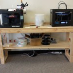
After looking at the various filaments that were available, we decided that we would use the Flashforge Creator Pro because it was open source, meaning we could customize the slicing settings easily, and because the extruder was a direct drive extruder, unlike the See-Me-CNC Rostock, which has a Bowden extruder. The filament choices that we considered were NinjaTek's NinjaFlex and NinjaTek's SemiFlex.
Material Comparisons
Without the change to physically see and compare the materials, we had to do some research. We found that NinjaFlex was the hardest to use by far, and that it often had problems with feeding through an extruder. Since we didn't want to modify our extruder, NinjaFlex was almost immediately eliminated.
That left SemiFlex, or looking into another flexible filament. Many of the reviews we read indicated that SemiFlex could be used on an unmodified direct drive extruder. Our Flashforge Creator Pro is an open source printer with a direct drive extruder, so we thought that would work well. We had also read success stories of its use on that particular printer. The fact that we didn't need to modify the extruder and that the filament had been used on one of our printers is why we chose to look no further than SemiFlex.
SemiFlex is available in quite a few colors. The color we chose is called "Water," which is essentially just a natural, translucent filament color. You can see pictures of the printed bracelets below.
Design Iterations

Design One
Everything was designed by me on a student license of Autodesk Inventor.
This first design was made with the idea of printing the band in one print, then the planets as snap-on pieces. The students would be able to paint each planet, wait for them to dry, then snap them on to the band for the finished bracelet. The goal was to make flat surfaces for easy printing.
Most of the printing time for this design was spent trying to get the settings for the filament dialed in.

Design Two
In the second design, we decided to make the bottom of the planets flush with the bottom of the bracelet. This allowed the bracelet to be printed in one piece, and there was no concern of the planets not staying on.
The major issue with this design was that the band was too thick. The flexible filament did bend but only under pressure. As soon as you stopped holding it in a circle, the bracelet would try to bend back into the flat shape. The other issue was that the hook didn't stay in the other end of the bracelet when you tried to clasp it together.

Design Three
In this design, the band is thinner, and the hook is a closed loop. To allow it to clasp, we used cutting pliers to create a very thin break in the loop, but the hook naturally returns to being closed rather than bending.
The band was lengthened slightly, and the planets sizes were somewhat adjusted. This is the final version that we went with for the students.
The total length is 190 mm. This allows the bracelet to be loose, and for the clasp to overlap. We printed some larger ones at about 220 mm for the adults. If we were to redo this, we should have lengthened all of them - the 190 mm was still too small for the middle schoolers.
The total printing time was about 40 hours, and the total filament usage was practically 1kg.
The Completed STL File
Downloadable File
Printed Bracelets
An Unpainted Bracelet
This bracelet is printed from the third iteration of the design. The ring has already been cut so that the bracelet can hook together.
This image was captured in our light box, made by Rita!

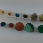
Painted Bracelets
These two bracelets were painted using acrylic paints. You can read more about coloring prints in our post about coloring 3D printed objects.
The one in the back is one of the first iteration prints. It was colored by Rita, who was testing if acrylic would work on the SemiFlex. The one in the front is one of the third iteration prints. It was painted by Jenny as her bracelet to keep as a souvenir from this experience.
This image was captured in our light box, made by Rita!