Tolerance

3D Printing Do’s and Don’t’s for BuildIT

Before We Begin

Understanding 3D Printing

For an object to be 3D print well, it is best if it is designed specifically for 3D printing. 3D models can be created as very intricate shapes, but it is important to keep in mind the limitations of the machines that will be used to realize the object, and design with those limitations in mind.

To fully understand the limitations, it is important to have a good understanding of the process of 3D printing. If you are a current affiliate of SDSU (student, faculty, staff), one way to learn is to attend an orientation session and then schedule a 3D print training, where we will teach you about the process of 3D printing in our space, as well as guide you through an example print. If you would like, you can schedule your training session for a small group of no more than 3 people.

If you are not an affiliate of SDSU or you are interested in learning more before your training session, you can read more about various aspects of 3D printing under the "Learn" tab at the top of the page.

3D Printing Do's and Don't's

DO: Consider The Tolerances of The Printers

Note: BuildIT uses millimeters exclusively. Please ensure that all models submitted to us are in millimeters for proper sizing.

All of the 3D printers in BuildIT have a nozzle diameter of 0.4mm, which means that the minimum horizontal dimensions that can be placed is 0.4mm. To optimize printing time, vertical "walls" of a part can be made multiples of 0.4mm, but never less than 0.4mm. If the width of an extrusion is designed to be less than 0.4mm, the program we use to prepare parts for printing will ignore that portion of the object and no plastic will be placed.

When designing parts that should fit together, it is important to know that PLA plastic (the material we use) tends to shrink by about 0.5mm during the printing process. If you are designing a part to fit inside another part, the outer part hole should be oversized by about 0.5mm, and the peg that fits inside should be the desired size, knowing both will shrink slightly.

For Print In Place models:
When designing models that should be able to separate or move, each of our printers have a different tolerance for how close two parts can be before they fuse and are unable to move. A good general rule is to leave a minimum separation of 0.4mm between two parts that should be able to move independently of each other.

Tolerance

DO: Design Large Flat Sides

3D printing places plastic from a bottom layer to a top layer. This means that a large, flat side is best for 3D printing. Think of how it would be best to 3D print a pyramid - the square should be at the bottom and the layers should progress vertically towards the point of the pyramid.

pyramid with arrow

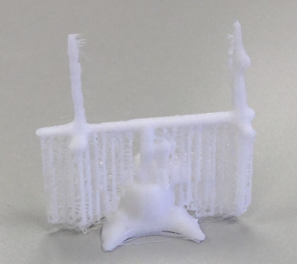
DON’T: Design Your Object With Small or Curved Sides

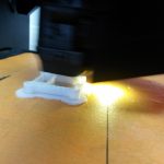
If your object does not have a large, flat side that can be oriented as the bottom layer, the printer will need to use Supports (or, in extreme cases, Rafts) to have a successful print. For some parts, if the object is too small, adding supports still won't allow a successful print. For other parts, if they are too large or require too many supports, adding supports may put the part over our 3-hour time limit, meaning we would not be able to print it.

Supports can be thought of as scaffolding on a building - they are extra plastic that is placed by the printer to support the structure of the object as it is being built, but they are designed to be easily removable after the object is complete. Supports are automatically generated by the slicing software, so you don't need to worry about designing them, but you do need to worry about removing them.

For small or thin parts, the act of removing supports can break the part. For other parts, the supports can end up enclosed within the part, and it will be impossible to remove them without breaking the part open. These are important design considerations for when you design objects that might need supports.

You may be wondering how you can create complex shapes while minimizing supports, which leads to the next point...

Quadrifolium 3D Print

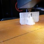
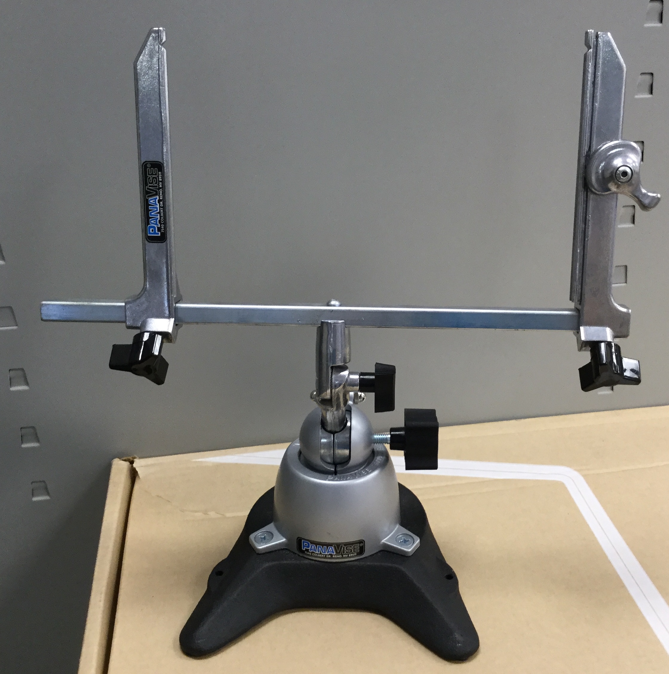
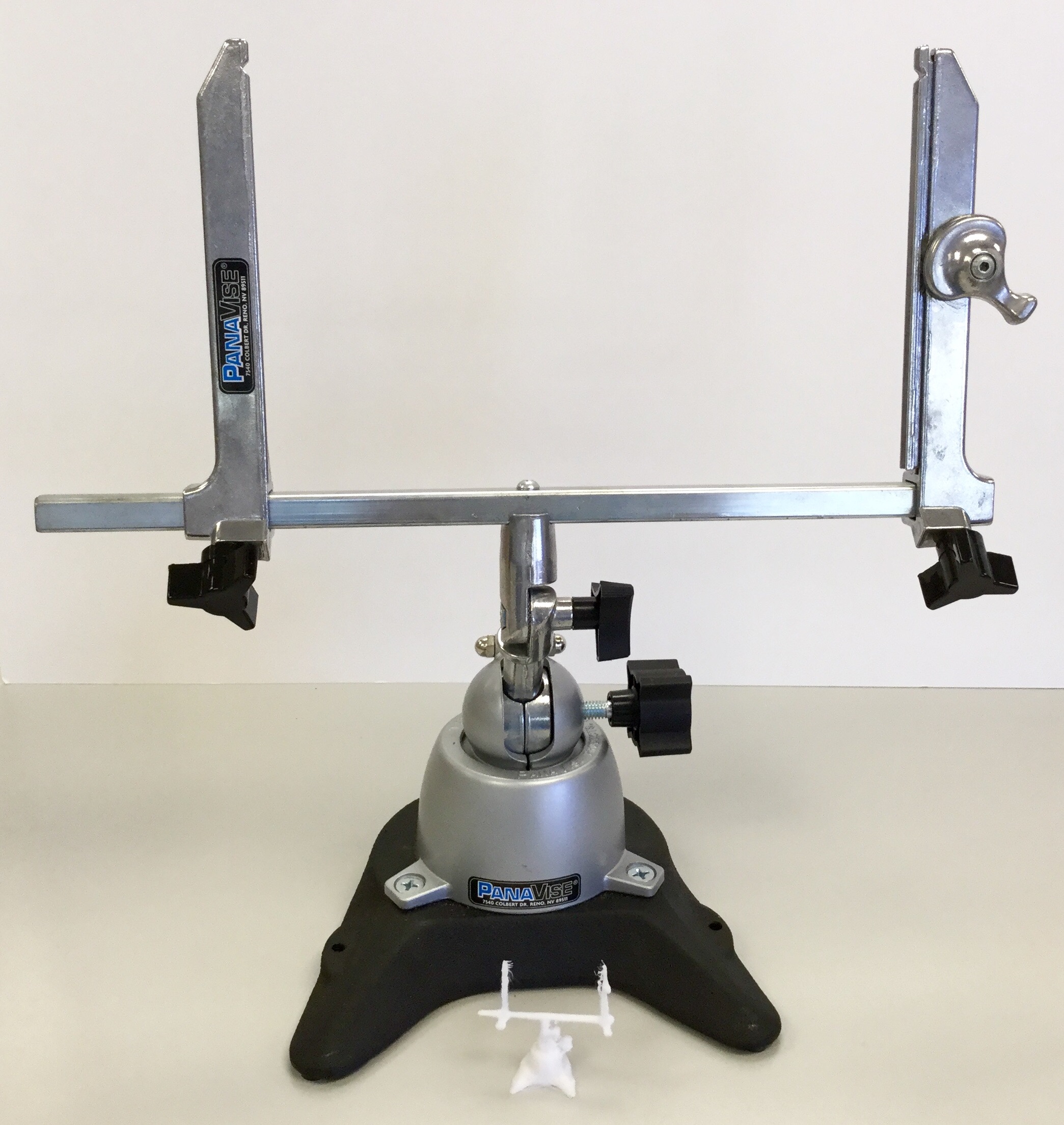
DO: Design Modular Parts

To minimize the need for supports, you can design your completed object as a group of parts that can be optimized for printing, then assembled into the complex shape that you actually need or want.

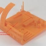
For example, the object at right was designed as 4 different flat pieces with clips that were all printed separately, then assembled into the complex shape that is shown. This is an excellent way to make completed objects that are too large for our printers or shapes that are too complex to print well. It does require extra work, but it's worth the effort for the better print quality you get in return.

Google Cardboard - Modular

DO: Ask Yourself If 3D Printing Makes Sense

There are some shapes that are easy enough to fabricate using other means that it doesn't really make sense to 3D print them. A very common example of this is a sheet of plastic with a few holes in it - it would be better to purchase a sheet of acrylic or polycarbonate ("Lexan") plastic, cut it to the size necessary, and drill the holes (using a hand drill or drill press). If you are an SDSU affiliate (student, faculty, staff), we have a desktop CNC router called Carvey that you can receive training on after you complete orientation, then have Carvey drill holes in precise locations on wood or acrylic (no polycarbonate or metal) pieces.

Another consideration for whether your object needs to be 3D printed is how dense you want the infill to be. Infill is the percentage of the inside that is filled with plastic, where the other percentage is air. For example, 0% infill means fully hollow, and 100% infill means fully solid. We have found that infill percentages above 30% jam our 3D printers, so we are only able to print 0% infill to 30% infill parts. If you need or want your part to be denser or solid, you should look into other means of manufacturing a part. Please note that you cannot drill into 3D printed parts at arbitrary locations because chances are that it is hollow at the point you choose to drill.

It is also important to consider the purpose of your object and what materials should (or should not) be used. We print exclusively in PLA, which starts to soften and become pliable around 60 degrees Celsius, and is generally a brittle material (PLA stress test). If your object will be experiencing a lot of impact or force (PLA 40km/h impact test video), or will end up in or near heat (for example, from motors), this may not be the best material to use. If PLA won't work for your purposes, 3D printing can be good for prototypes and size checks, but may not be good for your finished object.

Revised Plastic-Sheets
supports print

Supports

Before we begin

Necessary Terminology

Extruder - This is a part of a 3D printer. This is the part that heats up to nearly melt the material so that the material can be worked with. A motor pushes the material through the hot part and out of a nozzle at the end.

Filament - This is the material that is extruded. In the case of buildIT, we use a Polylactic Acid (PLA) plastic filament. For more information, please see the post about materials.

Print Bed/Build Plate - This is a part of a 3D printer. This is the part of the printer that the filament is extruded onto. On some of our printers, this is a heated plate with or without glass on top. On others, it is simply a glass plate.

Layer Height - This is the amount the extruder moves vertically between each layer of the print. This number is usually a fraction of a millimeter for our printers. For more information, please see the post about layer heights and resolutions.

What are supports?

Technical Description

Supports are extrusions of material that are continuously built up to prevent droop for an object or a part of an object where previous layers are insufficient to prevent droop on their own. The 'rule of 45°' is often used to determine when supports are necessary. This rule will be discussed below.

Explanation

Plastic cannot be deposited onto thin air - it needs something to sit on. Supports are extra bits of plastic that are put down as the printer moves through the layers. They can be thought of as temporary scaffolding for the part; supports are for the construction of a part to help it be built and are removed when the part is done. Since 3D printing is done in layers, the scaffolding is built up layer by layer as the part is.

Supports are necessary when the object has overhangs. An overhang is a piece of an object that does not have a layer directly beneath it. In other words, to attempt to print an overhang would be like trying to print onto thin air - there's nothing for the plastic to sit on. Supports remedy this by providing a temporary structure for the object's overhangs to be printed on.

When should I use supports?

The 45 Degree Rule

There is a general rule of thumb for when parts need supports called the "45 degree rule." It may be hard to think about the 45° Rule on a 3D model or object, so this section explains the concept, and the next section has an example.

The image to the right shows a plane. The vertical axis is at 0°, there's a line in the middle at 45°, and the horizontal axis is the 90°. If the overhang of a part is between 0° and 45° from vertical (the green curve on the picture to the right), supports are unnecessary. If the overhang of a part is between 45° and 90° from vertical (the red curve on the picture to the right), supports are required.

A variation of this uses 60° from the vertical as the cutoff for needing supports. We use 45° because it tends to be the easiest to visualize, and it works very well for making sure that all parts that need supports have them.

degrees

An Example

The image to the right is a screenshot of a model of a Darth Vader helmet by Jace1969 from Thingiverse. The arrows, two red and one green, point to three different locations where there is an overhang. These are not the only overhangs on this model, but they are the easiest to see.

The rightmost arrow is red. It points to a part of the object that doesn't have another part of the object directly beneath it, so it is an overhang, and it juts out from the part between 45° and 90° from vertical. This portion needs supports.

The center arrow is also red. It points to another overhang, This is also between 45° and 90° from vertical, so it also requires supports.

The leftmost arrow is green. The curve of the helmet is an overhang because there isn't another portion of the object directly beneath it. However, unlike the other two parts, this is between 0° and 45° from vertical, so no supports are necessary.

What do supports look like?

panavise

The Model

For this example, I decided to 3D scan a vice that we had on a workbench in buildIT. This is a picture I took of the model for our part.

For more information on 3D scanning, see our blog post about it!

Looking at the model, you'll notice that it has two arms at 90° to the vertical. This means that the printed version will require a lot of supports.

supports print

On the printer

The small vice was printed on the Makerbot printer with supports. The print was nearly done by the time this picture was taken.

The supports are completely done. The thinner-looking extrusions all along the sides are supports. They are meant to snap off easily once the part is removed from the printer.

supports on

Off the printer, on the part

This is how the part came off the printer. The supports are attached to the part - they move when the part does. However, they are very thin.

At this stage, it should be very easy to remove them. This part was a bit of a challenge because of how thin the actual part is. The majority of parts will have something much more substantial than the supports staying on the part, whereas this part was about as thin as the supports were.

supports off

Off the printer, off the part

The supports have been removed. The part is ready to be cleaned up with a hobby knife to get rid of any other excess filament.

The supports are now trash. They can be thrown away in a trash can or in our plastic recycling can.

Remember to clean up after yourself!

panavise

Comparison

This picture shows the completed and cleaned 3D printed version of the vice in front of the model.

I think they look pretty similar!

How Do I add supports?

Adding supports to a print is easy!

The way you add supports depends on the 3D printer you're using and its associated software.

A quick reminder on software association with printers:
• Rostock uses Cura
• Flashforge uses Cura
• Makerbot uses Makerbot Desktop
• CubePro uses CubePro

cura support1

To add supports using Cura

The two pictures show screenshots of Cura.

The picture on the left shows a green circle around "Support Type." Click on the dropdown selector next to "Support Type."

The picture on the right shows a red circle around the dropdown options. You have some choices based on your needs. Your choices are "Touching Buildplate" or "Everywhere." The main difference is whether your object has overhangs that you are concerned about above the base. If it doesn't, "Touching Buildplate" should be enough. In general, though, I usually choose "Everywhere."

cura support2

To add supports using Makerbot Desktop

The two pictures show screenshots of Makerbot Desktop.

The picture on the top shows a green circle around "Settings." Click on Settings.

The picture on the bottom shows a red circle around the checkbox on the settings menu next to "Support." Click so that the checkbox has a checkmark in it.

Makerbot Raft 1
makerbot support2
cube support1

To add supports using CubePro

The two pictures show screenshots of the CubePro software.

The picture on the left shows a green circle around "Build." Click on "Build" to begin changing settings.

The picture on the right shows a red circle around the "Support Material." The dropdown selector already says "PLA White." For the CubePro, "Support Material" simply means the material the supports will be made out of. The CubePro allows the user to select the color and filament material for the supports, which is why we have a color option. As we only load one cartridge of filament at a time, simply select whatever color it offers.

In the bottom of the red circle, you have the choice of support type: points, or lines. We always use "lines" because they offer the most stability and the best chance at a good print. This shouldn't be changed for printing here, but it's always good to check that the settings are what you expect before printing.

cube support2
filamentcolors

Materials for 3D Printing

Original image by Pete Prodoehl

Before we begin

Necessary Terminology

Extruder - This is a part of a 3D printer. This is the part that heats up to nearly melt the material so that the material can be worked with. A motor pushes the material through the hot part and out of a nozzle at the end.

Hot End - This is a part of a 3D printer. It is usually considered to be a part of the extruder. It is the part that actually heats up to melt the material. It is placed on a carriage that moves it around to place the material.

Filament - This is the material that is extruded.

Direct Drive Extruder - This is a type of extruder. In a direct drive extruder, the motor is placed on the carriage with the hot end. One drawback to a direct drive extruder is that it is heavier so the printer needs to move slower to achieve a nice print.

Bowden Extruder - This is a type of extruder. In a Bowden extruder, the motor is placed off of the carriage that the hot end is on. Filament is pushed through a tube to the carriage with the hot end. One benefit to the Bowden extruder is that the carriage is lighter so the printer can move faster and still achieve a nice print.

Print Bed/Build Plate - This is a part of a 3D printer. This is the part of the printer that the filament is extruded onto. On some of our printers, this is a heated plate with or without glass on top. On others, it is simply a glass plate.

Painters Tape - This may not seem like it, but this is an important part of 3D printing in buildIT. This material is the exact same as the one you would purchase for painting a room in your house. The tape is placed on the print bed so that the material has a rough surface to adhere to. If the tape wasn't there, the material would have a much harder time staying in place.

Layer Height - This is the amount the extruder moves vertically between each layer of the print. This number is usually a fraction of a millimeter for our printers. For more information, please see the post about layer height and resolution.

Warping - This is something that can happen to a print. In some prints, the edges of the part will curl up, away from the build plate. This can happen for a variety of reasons, including the part being too big or too thin. Usually, a part will need to be reprinted if the warping is severe enough. Some filament materials are more prone to warping than others.

Filament Basics

Most filaments…

Filaments tend to have some things in common for 3D printing. Most are plastic or plastic-based. Nearly all are put on spools to help keep them from getting tangled on their way into the extruder. Nearly all filament has a melting point between 180° and 250° Celsius.

Filament can come in 1.75mm or 3mm, but all of our printers have 1.75mm extruders. All filament that we use in buildIT is 1.75mm.

ABS

Original image by Creative Tools

ABS Material Basics

ABS stands for Acrylonitrile Butadiene Styrene. In the context of 3D printing, it is a plastic filament that comes on a spool. ABS is one of the two main printer filaments.

ABS is the material that LEGO bricks have traditionally been made of.

Print Temperature: 245° Celsius

Bed Temperature: 100° Celsius, if the bed heats up.

Print Speed: This varies by printer, but 40-50 mm/s works well.

Flow Rate: 100%

Toxicity: The fumes emitted by ABS are considered to be bad to inhale for large periods of time. Proper ventilation is strongly recommended when printing with ABS. The material is not recommended to be eaten. For more information, please see the Material Safety Data Sheet.

Cooling Fan: Do not use a cooling fan. The reason ABS is prone to warping is because it cools too quickly.

To help with adhesion: Painters tape can be put on the print surface to help with adhesion. If the painters tape by itself doesn't work well enough, putting down a small amount of glue from a glue stick may help. If the glue doesn't help enough, using a paint brush to put down some acetone may help. Dissolving some ABS in the acetone before painting it on can also be useful.

Discussion

ABS is not used in buildIT. This is for the simple reason that the fumes emitted by the melting ABS are toxic, and we do not have a sufficient ventilation system in place. We do not want the fumes to be trapped in our space, or expose patrons in the library to the fumes.

In printing, ABS tends to be prone to warping due to loss of heat. As it cools, the material tends to curl inwards. An easy way to help with this problem is to use a raft or put something on the print surface to help the object stick better.

ABS PRO

○ ABS parts tend to be rather strong once they are done printing.
○ More flexible than PLA (see next section), so somewhat more durable.
○ Relatively cheap, compared to other filaments besides PLA (see next section).

ABS CON

○ ABS is very prone to warping.
○ ABS emits fumes when heated that should not be inhaled if possible. This means that ventilation is required.
○ ABS is somewhat prone to layer separation.

PLA

Original image by Adafruit Industries

PLA Material Basics

PLA stands for Polylactic Acid. In the context of 3D printing, PLA is a plastic filament that comes on a spool. PLA is one of the two main printer filaments.

PLA has been used in disposable cups and utensils, as well as bags and food packaging.

Print Temperature: 215° Celsius

Bed Temperature: 60° Celsius, if the bed heats up.

Print Speed: This varies by printer, but 40-50 mm/s works well.

Flow Rate: 100%

To help with adhesion: Painters tape can be put on the print surface to help with adhesion. If the painters tape by itself doesn’t work well enough, putting down a small amount of glue from a glue stick may help.

Toxicity: It is not recommended to eat PLA, but small quantities can be ingested with minimal adverse effects. The odor given off by the melting PLA is also nontoxic. PLA is biodegradable. For more information, see the Material Safety Data Sheet.

Cooling Fan: If you have one, use it.

A neat trick: When unloading PLA, you can avoid a clog by heating the extruder to about 80° Celsius, disengaging the motor, and pulling the PLA out quickly.

Learn more about PLA

Discussion

PLA is the main material that we use in buildIT. This is because it emits relatively scentless fumes that are nontoxic. It is also pretty easy to work with, and can be colored nicely with a variety of methods. For more information on coloring PLA, please see the post about how to color prints.

PLA can be food-safe when the filament preparation process is specifically food-safe, and when printed on a specifically food-safe printer. The PLA and printers that we use in buildIT are not food-safe.

PLA PRO

○ PLA is nontoxic when heated.
○ PLA is relatively easy to work with when printing.
○ PLA can be food safe.
○ Relatively cheap, compared to other filaments besides ABS.
○ PLA is compatible with most printers.

PLA CON

○ PLA is relatively soft when the part is completed.
○ PLA has a low temperature at which it gets soft. This means that a completed object can lose its shape or structural integrity at a low temperature.
○ PLA tends to be more brittle than ABS, which may decrease durability.

NinjaTek - SemiFlex

Original image by Joey Casabar

SemiFlex Material Basics

NinjaTek's SemiFlex is a flexible filament material that we have used in buildIT. We used it for a project that we worked on for STEM Day. This material is not normally available for use.

Print Temperature: 225° Celsius

Bed Temperature: 60° Celsius, if the bed heats up.

Print Speed: This varies by printer, but 15-25 mm/s works well.

Flow Rate: 350%

Toxicity: The material is toxic if ingested, so one should avoid eating it. The fumes created when it is heated are relatively odorless, but breathing them should be avoided if possible. For more information, see the Material Safety Data Sheet.

Cooling Fan: If you have one, use it.

To help with adhesion: Painters tape can be put on the print surface to help with adhesion. If the painters tape by itself doesn't work well enough, putting down a small amount of glue from a glue stick may help.

For the best results: Slow down the printer, increase the flow rate, and use a direct-drive extruder (not a bowden).

Discussion

SemiFlex is not used in buildIT. This is because it tends to be a very difficult material to work with. Additionally, only one of our printers is physically able to print with SemiFlex, so offering SemiFlex is logistically difficult.

SemiFlex is a material that has very interesting properties. It can stretch some, but it can bend very easily even after being printed. We found that the thicker the part is the harder it is to bend, but that is to be expected. To color SemiFlex, acrylic paint covered with a clear sealing spray worked relatively well.

For more information on our project with SemiFlex, including why we chose to use SemiFlex over other flexible filaments, see our post about the Engineers Week Bracelets.

SemiFlex PRO

○ We did not have to modify our extruder to work with the SemiFlex. The printer we used was an unmodified Flashforge Creator Pro.
○ SemiFlex was flexible enough for our purposes.
○ The fumes emitted were relatively odorless.

SemiFlex CON

○ SemiFlex jams in the extruder easily. We helped the jamming problem by continuously unspooling some filament so that the extruder wasn't pulling directly on the spool.
○ SemiFlex is best printed on a Direct Drive extruder, while most newer printers have Bowden extruders.
○ Ventilation is recommended.

Nylon

Original image by Lindsay White

Nylon Material Basics

Nylon is a material that is not available in buildIT. This section is included because I have used nylon on my own personal 3D printer for my own personal project, so I have some experience with the settings that worked well for it.

The specific nylon that I used was Taulman Bridge in 3mm.

Print Temperature: 245° Celsius

Bed Temperature: 100° Celsius, if the bed heats up.

Print Speed: This varies by printer, but 20-40 mm/s works well.

Flow Rate: 100%

To help with adhesion: Painters tape can be put on the print surface to help with adhesion. If the painters tape by itself doesn't work well enough, putting down a small amount of glue from a glue stick may help.

Toxicity: It is not recommended to eat, but there are minimal adverse effects for ingesting small amounts. When heated for printing, the material gives off a strong odor but is considered nontoxic. For more information, see the Material Safety Data Sheet.

Cooling Fan: If you have one, use it.

Discussion

Nylon is not available for use in buildIT. This is because it has a very strong odor and is rather difficult to get a good print with.

Nylon is about as hard to work with as ABS. A heated build plate is strongly recommended because nylon is also very prone to warping. It fed through the printer without issue, but had some difficulty adhering to the build surface. It creates a stronger part than ABS did, and it is a little less rigid than ABS.

Nylon PRO

○ Nylon has more tensile strength than ABS, so it may be more durable.

Nylon CON

○ Nylon has a very strong odor when heated.
○ Ventilation is required when working with Nylon.
○ Nylon is very prone to warping.
○ Nylon must be stored with a way to remove moisture, else it will absorb the moisture in the atmosphere and become unusable.

Other Filaments

Original image of a 3D print in Laywood filament by Creative Tools

Filaments We Have Not Yet Used

There are many other filaments available for 3D printing. These filaments are not available to use in buildIT. We have not yet had a chance to try them out, but this is where I'll discuss what they are. As we have not used them, I will not include information on printer settings for the specific filaments.

Most other filaments are a composite, usually of PLA and another material. One really cool one is a composite of PLA and wood fibers that can be sanded and stained after the print is done, called Laywood. Another is a composite of PLA and stone particles that can be sanded, ground, and polished, called Laybrick.

NinjaTek, the makers of the SemiFlex filament that we have used previously, also make a variety of other flexible filaments. Their list of filaments can be seen here.

A Last Note

On some printers, there are two extruders. These printers are called "Dual Extruder Printers." On these printers, it is possible to load a filament that will be for the object into one extruder, and a different material that will be for supports and rafts in the other. The benefit of doing this is that it's possible to use filament that dissolves in water. This would aid in the cleanup process for the part.

For example, you could load PLA in one extruder and PVA water soluble filament into the other, print out your part, and wash it in water to clean it up. Unfortunately, we have not used dissolvable filament, and it is not available in buildIT.

For More Information

Other Resources

colored bracelets

Solar System Bracelets

Background Information

Engineers Week

Every year, there is a week called Engineers Week. The idea is to get K-12 students interested in engineering ideas, classes, majors, and careers. Some companies get involved - hosting tours, giving presentations, or otherwise exposing students to STEM.

This week comes from the idea that the earlier children are introduced to engineering, the more excited they'll be to learn about it. To learn more, see the DiscoverE Website.

Girls’ Day

One day within Engineers Week is called Girl Day. The purpose of this day is to introduce a young girl to engineering. The perception that STEM, and specifically engineering, is only for boys is challenged for the girls that participate.

MESA Program

On SDSU's campus, there is a program called the Mathematics, Engineering, Science Achievement (MESA) Program. This program works to help students learn and achieve by providing on-campus resources and events. The MESA Program also engages in outreach events to help younger students become interested in STEM. To learn more about the MESA Program, visit their website here.

On Girls Day 2016, the MESA Program brought 30 middle school girls to SDSU's campus for a variety of STEM workshops and discussions. build IT was one of the locations the girls visited. We hosted the girls for roughly an hour, during which they listened to a presentation on 3D printing, watched some 3D printers print, scanned their friends with our handheld 3D scanner, and painted some 3D printed bracelets. This post is about the design and creation process of the bracelets.

There was a news article about the MESA program and Girls Day! You can read it here!

The Design

Design Requirements

We spent a long time trying to decide what object to print for the girls. We wanted everyone to take something home, and for them to be able to decorate them while they were here. We also wanted the object to be STEM related. Whatever it was, we were going to work in a brief talk on it during our presentation. After discussing various different objects (keychains, planters, and model planes were all considered!), we finally settled on using a flexible filament to create bracelets.

We knew that there were going to be about 30 girls, plus chaperones. We wanted to have enough bracelets so that there was one for each girl, plus their chaperones, plus some extras. We ended up deciding on 45 bracelets.

Next, we knew that we needed to be able to 3D print everything within the three weeks that we had before the event, so the bracelets had to be physically small enough to allow us to print 45 during the hours we were open. In addition to that, we wanted them to use a small enough amount of plastic such that we could get all 45 made from a 1kg spool. (Filament usually comes in spools of 1kg, so the purpose of this was to spend the least amount of money.)

To summarize, our requirements were:
• A bracelet that was entirely 3D printed
• 45 bracelets were needed
• Printable within 3 weeks only during open hours
• Use only 1kg of plastic for all bracelets
• STEM-related in some way

How big is your wrist?

Since we were set on bracelets, the next question was how big do they need to be? We didn't know which grade the girls would primarily be from, just that they were middle schoolers. Middle school in San Diego is grades 6-8, or approximately ages 10-14.

So just how big is a 10-14 year old girl's wrist? There were some websites that had sizing charts for jewelry, like this one, but we weren't sure how accurate they were.

We decided to start polling people who came in to build IT about their wrist sizes. We used string and a ruler and recorded wrist sizes. We decided that the average wrist size was probably close enough for the middle schoolers. It ended up being right around 7 inches, or about 178 mm.

What will go on the bracelet?

One of our design requirements was that the bracelets be STEM-related in some way. We talked about getting rid of that requirement and writing "buildIT" on them, but that seemed too much like self-promotion and not enough like education. We found a very cool bracelet design on Thingiverse, but we wanted the bracelets to be designed by us.

We eventually settled on a solar system. We decided that we would make equally spaced planets that were different sizes. We needed them to be equally spaced, or else it looked very squished, and we couldn't do the sizing to scale because some planets are too small to even appear. We decided to make them so that the larger planets were still larger, but not as much as they really are.

This gave us our talking points - 3D printing, space, and planets.

Which Filament to use?

Decisions, decisions…

We knew we wanted a flexible filament and that we wanted it to be easy to paint. For the second desire, we chose to use the natural color, so that the girls could paint the bracelets without worrying about a base color showing through.

For choosing the actual flexible filament, we had to go through a lot of considerations:
• the printers we had available and their extruders
• how flexible the completed bracelet needed to be
• how sturdy the completed bracelet needed to be

After looking at the various filaments that were available, we decided that we would use the Flashforge Creator Pro because it was open source, meaning we could customize the slicing settings easily, and because the extruder was a direct drive extruder, unlike the See-Me-CNC Rostock, which has a Bowden extruder. The filament choices that we considered were NinjaTek's NinjaFlex and NinjaTek's SemiFlex.

Material Comparisons

Without the change to physically see and compare the materials, we had to do some research. We found that NinjaFlex was the hardest to use by far, and that it often had problems with feeding through an extruder. Since we didn't want to modify our extruder, NinjaFlex was almost immediately eliminated.

That left SemiFlex, or looking into another flexible filament. Many of the reviews we read indicated that SemiFlex could be used on an unmodified direct drive extruder. Our Flashforge Creator Pro is an open source printer with a direct drive extruder, so we thought that would work well. We had also read success stories of its use on that particular printer. The fact that we didn't need to modify the extruder and that the filament had been used on one of our printers is why we chose to look no further than SemiFlex.

SemiFlex is available in quite a few colors. The color we chose is called "Water," which is essentially just a natural, translucent filament color. You can see pictures of the printed bracelets below.

Design Iterations

bracelet v1

Design One

Everything was designed by me on a student license of Autodesk Inventor.

This first design was made with the idea of printing the band in one print, then the planets as snap-on pieces. The students would be able to paint each planet, wait for them to dry, then snap them on to the band for the finished bracelet. The goal was to make flat surfaces for easy printing.

Most of the printing time for this design was spent trying to get the settings for the filament dialed in.

bracelet v2

Design Two

In the second design, we decided to make the bottom of the planets flush with the bottom of the bracelet. This allowed the bracelet to be printed in one piece, and there was no concern of the planets not staying on.

The major issue with this design was that the band was too thick. The flexible filament did bend but only under pressure. As soon as you stopped holding it in a circle, the bracelet would try to bend back into the flat shape. The other issue was that the hook didn't stay in the other end of the bracelet when you tried to clasp it together.

bracelet v3

Design Three

In this design, the band is thinner, and the hook is a closed loop. To allow it to clasp, we used cutting pliers to create a very thin break in the loop, but the hook naturally returns to being closed rather than bending.

The band was lengthened slightly, and the planets sizes were somewhat adjusted. This is the final version that we went with for the students.

The total length is 190 mm. This allows the bracelet to be loose, and for the clasp to overlap. We printed some larger ones at about 220 mm for the adults. If we were to redo this, we should have lengthened all of them - the 190 mm was still too small for the middle schoolers.

The total printing time was about 40 hours, and the total filament usage was practically 1kg.

The Completed STL File

WebGL Error

Downloadable File

In order to download the stl file to print your own, click here.

Printed Bracelets

An Unpainted Bracelet

This bracelet is printed from the third iteration of the design. The ring has already been cut so that the bracelet can hook together.

This image was captured in our light box, made by Rita!

uncolored bracelet

Painted Bracelets

These two bracelets were painted using acrylic paints. You can read more about coloring prints in our post about coloring 3D printed objects.

The one in the back is one of the first iteration prints. It was colored by Rita, who was testing if acrylic would work on the SemiFlex. The one in the front is one of the third iteration prints. It was painted by Jenny as her bracelet to keep as a souvenir from this experience.

This image was captured in our light box, made by Rita!

colored bracelets
Raft on Makerbot

Rafts

Before We Begin

Necessary Terminology

Extruder - This is a part of a 3D printer. This is the part that heats up to nearly melt the material so that the material can be worked with. A motor pushes the material through the hot part and out of a nozzle at the end.

Filament - This is the material that is extruded. In the case of buildIT, we use a Polylactic Acid (PLA) plastic filament. For more information, please see the post about materials.

Print Bed/Build Plate - This is a part of a 3D printer. This is the part of the printer that the filament is extruded onto. On some of our printers, this is a heated plate with or without glass on top. On others, it is simply a glass plate.

Painters Tape - This may not seem like it, but this is an important part of 3D printing in buildIT. This material is the exact same as the one you would purchase for painting a room in your house. The tape is placed on the print bed so that the material has a rough surface to adhere to. If the tape wasn't there, the material would have a much harder time staying in place.

Layer Height - This is the amount the extruder moves vertically between each layer of the print. This number is usually a fraction of a millimeter for our printers. For more information, please see the post about resolution and layer height.

Warping - This is something that can happen to a print. In some prints, the edges of the part will curl up, away from the build plate. This can happen for a variety of reasons, including the part being too big or too thin. Usually, a part will need to be reprinted if the warping is severe enough.

What is a raft?

Technical Description

A raft is an extrusion at the beginning of a print to help a part better adhere to the build plate. Prints that fail due to warping or detachment usually require reprints with rafts.

Explanation

A raft is some extra plastic that a 3D printer lays down before starting the actual part. The printer lays down about 3 layers in a very simplistic pattern on the build plate. The reasoning is very simple - even with the painters tape, plastic sticks best to other plastic. The idea behind a raft is to give the plastic something solid to attach to before creating the part. The layer height between the raft and the bottom layer of the part is larger than the rest of the layer heights. The idea is to make the raft easy to remove from the part when the part is done.

In the simplest terms, a raft is temporary, extra plastic that the printer lays down before starting the actual part to help the part adhere to the build plate. It is meant to be removed immediately after the print finishes.

When should I use a raft?

Steps to determine if a raft is necessary.

Once you gain some familiarity with the printer you're using and you've printed a few things, you'll start getting a sense on whether a part needs a raft before you try printing it. I'll discuss certain types of objects that usually need rafts below. Until you get an intuitive feel about rafts, though, there's an easy process to follow to figure out if you need a raft.

1. Try printing the object on the build plate without a raft. Consider adding glue if you have any doubts!

2. If the object doesn't stick to the build plate, becomes detached after a few layers, or starts warping, cancel the print immediately.

3. Assess why the print didn't go as planned. Did the printer have trouble extruding? Did you not use glue? Is there some mechanical problem that might have caused a failure?

4. If you've determined that there was no failure other than a lack of raft, add a raft and reprint!

Typical prints that require rafts

There are some prints that almost always require a raft in order to succeed. As stated above, getting a good sense of what needs a raft and what doesn't only truly comes from experience.

A raft is typically needed if:
• the object is smaller than about 10 mm in any direction at the base
• the object is thinner than about 3 layers at the extremities
• the object is larger than about 80 mm in any direction at the base

Essentially, a raft is needed if a part is too big, too small, or too thin.

What does a raft look like?

Raft on Makerbot

On the Printer

This is a picture of an object being printed on the Makerbot with a raft. This object is tc_fea's Miniature Castle from Thingiverse.

You can see that there is a large flat part, and a smaller part that extends further vertically. The large, flat part is the raft. The smaller part is the object. They are connected for now.

Part with Raft

Off the printer, on the part

At this stage, the part and the raft have been removed from the printer but not separated. It should be very easy to remove the raft from the object.
Part and Raft

Off the printer, off the part

The raft and the object have now been separated! At this stage, the object is completed. The raft is now trash. It can be disposed of in a trash can or in our plastic waste bin.

Remember to clean up after yourself!

How do I add a raft?

Adding a raft is easy!

The way you add a raft depends on the 3D printer you're using and its associated software.

A quick reminder on software association with printers:
• Rostock uses Cura
• Flashforge uses Cura
• Makerbot uses Makerbot Desktop
• CubePro uses CubePro

To add a raft using Cura

The two pictures show screenshots of Cura.

The picture on the top shows a green circle around "Platform Adhesion Type." Click on the dropdown selector next to "Platform Adhesion Type."

The picture on the bottom shows a red circle around the dropdown options. Click on "Raft."

Cura Raft 1
Cura Raft 2

To add a raft using Makerbot Desktop

The two pictures show screenshots of Makerbot Desktop.

The picture on the top shows a green circle around "Settings." Click on Settings.

The picture on the bottom shows a red circle around the checkbox on the settings menu next to "Raft." Click so that the checkbox has a checkmark in it.

Makerbot Raft 1
Makberbot Raft 2

To add a raft using CubePro

The two pictures show screenshots of the CubePro software.

The picture on the top shows a red circle around "Build." Click on "Build" to begin changing settings.

The picture on the bottom shows a red circle around the "Sidewalk Material" and a green circle around "PLA White." For the CubePro, "Sidewalk Material" simply means the material the raft will be made out of. The CubePro allows the user to select the color and filament material for the rafts, which is why we have a color option. As we only load one cartridge of filament at a time, simply select whatever color it offers.

CubePro Raft 1
CubePro Raft 2